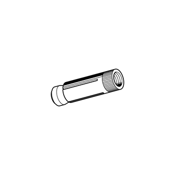
Hollow Core Anchor AN Easy
Application
Internal thread anchor to be used in pre-stressed hollow concrete slabs.
Suitable for suspension of pipe lines, channels, etc. considering the approval regulations for the use with threaded rods or screw. Only to be used with construction components under dry indoor conditions. The general technical approval allows the anchor to be installed even if the drill hole does not hit the cavity.
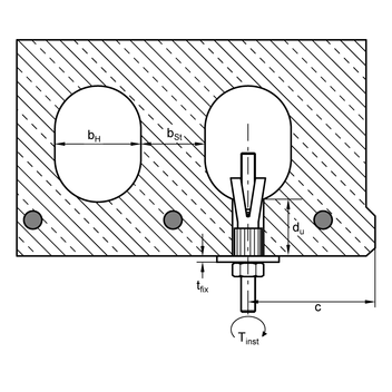
Installation
Tightening the screw or nut pulls the expansion cone inside the anchor sleeve which keys into the cavity. The anchor spreads Y-shaped inside the hollow space and using the specified torque gives secure form closure.
Technical Data
General installation parameters:
| Anchor size | M8 | M10 | M12 |
|---|---|---|---|
| Drill hole dia. d0 = [mm] | 12 | 16 | 18 |
| Depth of drill hole h0 = [mm] | 55 | 60 | 70 |
| Clearance hole in the fixture df ≤ [mm] | 9 | 12 | 14 |
| Minimum length of screw min ls 3) [mm] | 47 | 55 | 61 |
| Minimum lenght of stud min ls 3) [mm] | 53 | 63 | 71 |
| Installation torque Tinst = [Nm] | 20 | 30 | 40 |
| Minimum strength of screw/stud ≥ | 5.8 | 5.8 | 5.8 |
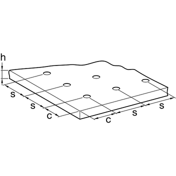
| Character. centre distance scr [mm] | 300 | 300 | 300 |
| Character. edge distance ccr [mm] | 150 | 150 | 150 |
| Minimum edge distance cmin [mm] | 100 | 100 | 100 |
Admission requirement for single anchor used in pre-stressed hollow concrete slabs ≥ C45/55:
| Anchor size Web thickness db ≥ [mm] | M8 25 | M8 30 | M8 40 | M8 50 | M10 25 | M10 30 | M10 40 | M10 50 |
|---|---|---|---|---|---|---|---|---|
| Perm. load 1) at c ≥ ccr [kN] | 0.7 | 0.9 | 2.0 | 3.6 | 0.9 | 1.2 | 3.0 | 3.6 |
| Perm. load 1) at cmin [kN] | 0.35 | 0.8 | 1.8 | 3.0 | 0.8 | 1.0 | 2.7 | 3.0 |
| Loads under fire exposure | ||||||||
| Perm. load R 30 perm. F [kN] | 0.9 | 0.9 | 0.9 | 1.2 | 1.5 | 1.5 | ||
| Perm. load R 60 perm. F [kN] | 0.9 | 0.9 | 0.9 | 1.2 | 1.5 | 1.5 | ||
| Perm. load R 90 perm. F [kN] | 0.7 | 0.7 | 0.7 | 1.2 | 1.2 | 1.2 | ||
| Perm. load R 120 perm. F [kN] | 0.4 | 0.4 | 0.4 | 1.0 | 1.0 | 1.0 |
| Anchor size Web thickness db ≥ [mm] | M12 25 | M12 30 | M12 40 | M12 50 |
|---|---|---|---|---|
| Perm. load 1) at c ≥ ccr [kN] | 1.0 | 1.2 | 3.0 | 4.3 |
| Perm. load 1) at cmin [kN] | 0.8 | 1.0 | 2.7 | 3.6 |
| Loads under fire exposure | | |||
| Perm. load R 30 perm. F [kN] | 1.2 | 1.5 | 1.5 | |
| Perm. load R 60 perm. F [kN] | 1.2 | 1.5 | 1.5 | |
| Perm. load R 90 perm. F [kN] | 1.2 | 1.5 | 1.5 | |
| Perm. load R 120 perm. F [kN] | 1.2 | 1.2 | 1.2 |
Admission requirement pair of anchors 4) pre-stressed hollow concrete slabs ≥ C45/55:
| Anchor size Web thickness db ≥ [mm] | M8 25 | M8 30 | M8 40 | M8 50 | M10 25 | M10 30 | M10 40 | M10 50 |
|---|---|---|---|---|---|---|---|---|
| Perm. load 1) at c ≥ ccr [kN] | 0.7 | 1.4 | 2.6 | 4.8 | 1.1 | 2.0 | 4.8 | 4.8 |
| Perm. load 1) at cmin [kN] | 0.35 | 1.25 | 2.35 | 4.0 | 0.9 | 1.8 | 4.3 | 4.3 |
| Minimum centre distance smin [mm] | 70 | 80 | 100 | 100 | 70 | 80 | 100 | 100 |
| Perm. bending moments (Steel 5.8)2) Madm. [Nm] | 10.7 | 10.7 | 10.7 | 10.7 | 21.4 | 21.4 | 21.4 | 21.4 |
| Perm. bending moments (Steel 8.8) Madm [Nm] | 17.1 | 17.1 | 17.1 | 17.1 | 34.2 | 34.2 | 34.2 | 34.2 |
| Loads under fire exposure | ||||||||
| Perm. load R 30 perm. F [kN] | 1.25 | 1.25 | 1.25 | 1.8 | 3.0 | 3.0 | ||
| Perm. load R 60 perm. F [kN] | 1.25 | 1.25 | 1.25 | 1.8 | 3.0 | 3.0 | ||
| Perm. load R 90 perm. F [kN] | 1.25 | 1.25 | 1.25 | 1.8 | 2.4 | 2.4 | ||
| Perm. load R 120 perm. F [kN] | 0.8 | 0.8 | 0.8 | 1.8 | 2.0 | 2.0 |
| Anchor size Web thickness db ≥ [mm] | M12 25 | M12 30 | M12 40 | M12 50 |
|---|---|---|---|---|
| Perm. load 1) at c ≥ ccr [kN] | 1.2 | 2.0 | 4.8 | 5.7 |
| Perm. load 1) at cmin [kN] | 1.0 | 1.8 | 4.3 | 4.8 |
| Minimum centre distance smin [mm] | 70 | 80 | 100 | 100 |
| Perm. bending moments (Steel 5.8)2) Madm. [Nm] | 37.4 | 37.4 | 37.4 | 37.4 |
| Perm. bending moments (Steel 8.8) Madm. [Nm] | 59.8 | 59.8 | 59.8 | 59.8 |
| Loads under fire exposure | | |||
| Perm. load R 30 perm. F [kN] | 1.8 | 3.0 | 3.0 | |
| Perm. load R 60 perm. F [kN] | 1.8 | 3.0 | 3.0 | |
| Perm. load R 90 perm. F [kN] | 1.8 | 3.0 | 3.0 | |
| Perm. load R 120 perm. F [kN] | 1.8 | 2.4 | 2.4 |
| 1) | For edge distances cmin < c ≤ ccr the recommended loads can be determined by linear interpolation. |
| 2) | Using lower strength classes, the value is to be reduced accordingly. |
| 3) | The required screw length is determined by the minimum length of screw + the thickness of the fixture tfix (total length = ls + tfix ) |
| 4) | Approved load Fmax / Anchor ≤ Fmax single anchor. On double anchorage with spacing smin < s ≤ scr the recommended load may be determined by linear interpolation, assuming the limiting value s = scr for the double anchorage exposed to tension is twice the recommended load of a single anchor. |
| Material: | Steel, zinc-plated |
Approvals / Conformity
Approval: Z-21.1-1785, Fire Protection Eximantion, VdS-Approval
![]()

1) Liefertermin auf Anfrage – Ware wird auftragsbezogen beschafft.